In the realm of motor driver circuits, the flyback diode serves a crucial and often underappreciated role. As a trusted supplier of motors and drivers, we understand the significance of every component in ensuring the efficient and reliable operation of motor systems. In this blog, we will delve into the function of a flyback diode in a motor driver circuit, exploring its importance, working principles, and practical applications.
Understanding the Basics of a Motor Driver Circuit
Before we dive into the role of the flyback diode, let's first understand the basic components and operation of a motor driver circuit. A motor driver circuit is designed to control the speed, direction, and torque of an electric motor. It typically consists of a power supply, a control circuit, and a power stage. The power supply provides the necessary electrical energy to the motor, while the control circuit generates the appropriate signals to control the motor's operation. The power stage, which includes transistors or MOSFETs, switches the power to the motor based on the control signals.
Motors, especially inductive loads like DC motors, stepper motors, and servo motors, have a unique characteristic: they store energy in their magnetic fields. When the current flowing through a motor is suddenly interrupted, the magnetic field collapses, inducing a high-voltage spike in the opposite direction of the original current flow. This phenomenon is known as back electromotive force (EMF) or inductive kickback.
The Problem of Inductive Kickback
Inductive kickback can pose significant challenges to the motor driver circuit and other components in the system. The high-voltage spike generated by the collapsing magnetic field can exceed the voltage ratings of the transistors or MOSFETs in the power stage, leading to their damage or failure. Additionally, the voltage spike can cause electromagnetic interference (EMI), which can disrupt the operation of other electronic devices in the vicinity.
To illustrate the problem, consider a simple DC motor driver circuit using a single transistor to control the motor. When the transistor is turned on, current flows through the motor, creating a magnetic field. When the transistor is turned off, the magnetic field collapses, inducing a high-voltage spike across the motor terminals. This voltage spike can damage the transistor and other components in the circuit.
The Function of a Flyback Diode
A flyback diode, also known as a freewheeling diode or snubber diode, is a simple yet effective solution to the problem of inductive kickback. It is connected in parallel with the inductive load (the motor) in a reverse-biased configuration. When the current flowing through the motor is interrupted, the flyback diode provides a low-resistance path for the induced current to flow, allowing the energy stored in the magnetic field to dissipate safely.


Here's how a flyback diode works in a motor driver circuit:
- During normal operation: When the motor is running, the flyback diode is reverse-biased, meaning it does not conduct current. The current flows through the motor as normal, and the diode has no effect on the circuit.
- When the current is interrupted: When the power to the motor is turned off or the current is suddenly interrupted, the magnetic field in the motor collapses, inducing a high-voltage spike. The flyback diode becomes forward-biased, allowing the induced current to flow through it in a closed loop. This current gradually decays as the energy stored in the magnetic field is dissipated as heat in the diode and the motor windings.
By providing a path for the induced current, the flyback diode prevents the high-voltage spike from damaging the transistors or MOSFETs in the power stage. It also reduces EMI by suppressing the voltage spikes and minimizing the electromagnetic radiation generated by the collapsing magnetic field.
Types of Flyback Diodes
There are several types of diodes that can be used as flyback diodes, each with its own characteristics and applications. The most commonly used types include:
- Schottky diodes: Schottky diodes have a low forward voltage drop and fast switching speed, making them ideal for applications where high efficiency and fast response times are required. They are commonly used in high-frequency motor driver circuits and switching power supplies.
- Standard rectifier diodes: Standard rectifier diodes are inexpensive and widely available. They have a higher forward voltage drop and slower switching speed compared to Schottky diodes, but they are suitable for low-frequency applications where cost is a major consideration.
- Fast recovery diodes: Fast recovery diodes have a faster switching speed than standard rectifier diodes, making them suitable for applications where the current is interrupted frequently. They are commonly used in motor driver circuits and other applications where high-speed switching is required.
Practical Applications of Flyback Diodes
Flyback diodes are used in a wide range of motor driver circuits, including:
- DC motor driver circuits: In DC motor driver circuits, flyback diodes are used to protect the transistors or MOSFETs from inductive kickback. They are typically connected in parallel with the motor terminals or across the power stage switches.
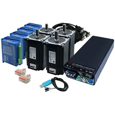
- Stepper motor driver circuits: Stepper motors are commonly used in applications where precise control of position and speed is required, such as robotics, CNC machines, and 3D printers. Flyback diodes are used in stepper motor driver circuits to protect the driver chips and other components from inductive kickback. For example, our Nema23 Close Loop Stepper Motor and 2 PHASE Stepper Motor driver circuits incorporate flyback diodes to ensure reliable operation.
- Servo motor driver circuits: Servo motors are used in applications where high torque and precise control are required, such as industrial automation, robotics, and aerospace. Flyback diodes are used in servo motor driver circuits to protect the power transistors and other components from inductive kickback. Our 3.8kw Servo driver circuits are designed with flyback diodes to provide reliable and efficient operation.
Choosing the Right Flyback Diode
When choosing a flyback diode for a motor driver circuit, several factors need to be considered, including:
- Voltage rating: The voltage rating of the flyback diode should be higher than the maximum voltage that can be induced across the motor terminals. This ensures that the diode can withstand the high-voltage spike generated by the collapsing magnetic field without breaking down.
- Current rating: The current rating of the flyback diode should be higher than the maximum current that can flow through the motor. This ensures that the diode can handle the induced current without overheating or failing.
- Switching speed: The switching speed of the flyback diode should be fast enough to respond to the sudden changes in current flow. This is especially important in high-frequency motor driver circuits where the current is interrupted frequently.
Conclusion
In conclusion, the flyback diode plays a critical role in protecting motor driver circuits from the damaging effects of inductive kickback. By providing a low-resistance path for the induced current to flow, the flyback diode prevents high-voltage spikes from damaging the transistors or MOSFETs in the power stage and reduces EMI. As a leading supplier of motors and drivers, we understand the importance of using high-quality flyback diodes in our products to ensure reliable and efficient operation.
If you are in the market for motors and drivers, we invite you to explore our wide range of products, including Nema23 Close Loop Stepper Motor, 2 PHASE Stepper Motor, and 3.8kw Servo. Our team of experts is ready to assist you in choosing the right products for your application and providing you with the support you need to ensure a successful installation. Contact us today to start a procurement discussion and take your motor-driven projects to the next level.
References
- Boylestad, R. L., & Nashelsky, L. (2012). Electronic Devices and Circuit Theory. Pearson.
- Scherz, P., & Monk, S. (2016). Practical Electronics for Inventors. McGraw-Hill Education.
- Tietze, U., & Schenk, C. (2008). Electronic Circuits: Handbook for Design and Application. Springer.