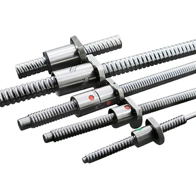
A servo axis tunes badly when the motor cannot feel the load. The inertia ratio predicts that before you touch a gain, and it is calculated from four numbers you already have.
Why the Inertia Ratio Decides Tuning Success
A servo axis is a control loop trying to move a mass. The loop can only work well when the motor can feel what the load is doing. If the load is much heavier than the motor expects, the motor moves before the load does, the loop over-corrects, and you spend days adjusting gains that were never the problem.
The number that describes this mismatch is the inertia ratio: the total reflected load inertia divided by the motor's own rotor inertia. Calculate it before you order the motor, not after the machine is built and will not settle.
Load Inertia for a Rotating Cylinder
For a solid or hollow cylinder turning about its own axis, inertia is:
J = ½ · m · r²
where m is mass in kg and r is the outer radius in metres. For a hollow cylinder with inner radius rᵢ and outer radius r₀, use ½ · m · (rᵢ² + r₀²). A ball screw is treated as a solid cylinder of its root diameter, which slightly overestimates inertia and is the safe direction for sizing.
Calculate mass from geometry rather than from the catalogue weight, because the catalogue figure includes the machined ends and can differ from the modelled length by a few percent. For steel, mass = π · r² · L · 7850.
Load Inertia for a Moving Mass on a Ball Screw
A table, a slide or a gantry moving linearly on a screw has an equivalent rotary inertia at the screw:
J = m · (p / 2π)²
where m is the moving mass in kg and p is the screw lead per revolution in metres. This is the single most useful formula for machine designers, because it shows that inertia falls with the square of the lead. Halving the lead cuts the reflected inertia of the moving mass to a quarter, at the cost of doubling the speed needed for the same feed rate.
Total load inertia at the motor shaft is the sum of the screw inertia and the moving mass inertia, plus any pulley or coupling inertia.
Reflected Inertia Through a Gearbox
If a reducer sits between the motor and the load, load inertia is divided by the square of the ratio:
J_reflected = J_load / i²
This is why a gearbox is the standard fix for an axis with too much inertia. A 10:1 reducer cuts the reflected load inertia by a factor of one hundred. The cost is speed and a small amount of added backlash, which matters more on a positioning axis than on a feed axis.
Remember that the gearbox's own inertia reflects to the motor at 1:1, so a large gearbox can negate part of the benefit at low ratios.
What Ratio to Aim For
| Ratio (load : motor) | Practical meaning | When it is acceptable |
|---|---|---|
| 1:1 to 3:1 | Easy to tune, stiff response, fast settling. | Default target for positioning axes |
| 3:1 to 5:1 | Tunable with normal auto-tuning. Slight loss of bandwidth. | Most machine axes |
| 5:1 to 10:1 | Requires manual tuning. Settling time grows, overshoot appears. | Low-dynamic axes, slow feed, no fast reversal |
| Over 10:1 | Difficult to stabilise. Resonance and audible noise at speed. | Only with a gearbox or a much larger motor |
These bands assume a rigid mechanical train. A long belt, a flexible coupling or a screw with backlash behaves like a spring between motor and load, which makes a low ratio behave worse than the number suggests. Fix the mechanics before chasing the ratio.
Symptoms of a Bad Ratio
A ratio that is too high announces itself in ways that are easy to misdiagnose:
- Audible whine or growl at a specific speed, which is resonance rather than a bearing problem.
- Overshoot on stopping that cannot be tuned out without making the axis sluggish.
- Position error that grows with acceleration but is fine at constant feed.
- Auto-tuning completing but leaving gains unusually low.
- Motor rated current reached during acceleration with almost no load on the machine.
If two or more of these appear together, measure the ratio before replacing anything.
Fixing It: Gearbox, Larger Motor or Lighter Load
Three options, in ascending order of cost and disruption:
Reduce the moving mass. Often the cheapest. A lighter carriage or a shorter screw sometimes brings the ratio into range with no hardware change at all.
Reduce the lead. Because moving-mass inertia falls with the square of the lead, going from a 20 mm lead to a 10 mm lead cuts that component to a quarter. This is the option most designers overlook.
Add a gearbox or a larger motor. A reducer divides load inertia by the square of its ratio, which is far more effective than stepping up the motor size. A larger motor also raises its own inertia, which helps the ratio but costs current and space.
Worked Example: Ball Screw Axis
Horizontal axis, 20 mm diameter steel screw, 1,000 mm long, carrying a 50 kg carriage, 10 mm lead, direct coupled to a 400 W servo with rotor inertia around 0.5 × 10⁻⁴ kg·m².
- Screw mass: π × 0.01² × 1.0 × 7850 ≈ 2.47 kg
- Screw inertia: ½ × 2.47 × 0.01² ≈ 1.24 × 10⁻⁴ kg·m²
- Carriage inertia: 50 × (0.010 / 2π)² ≈ 1.27 × 10⁻⁴ kg·m²
- Total load inertia: ≈ 2.51 × 10⁻⁴ kg·m²
- Ratio: 2.51 / 0.5 ≈ 5:1
Five to one is workable with normal tuning. If the carriage doubled to 100 kg, the ratio would climb to roughly 7.5:1 and the axis would start to show overshoot. Switching that same axis to a 5 mm lead would bring the carriage component down to a quarter of its value and put the ratio back near 3:1.
Frequently Asked Questions
Is a lower inertia ratio always better?
No. Very low ratios mean a large motor relative to the load, which costs money and current. Three to five to one is the usual sweet spot for machine axes.
Does the coupling inertia matter?
On small axes, yes. A metal bellows coupling on a 100 W axis can be a noticeable fraction of total inertia. On a 400 W axis it is usually negligible.
Can I measure the ratio instead of calculating it?
Yes. Many drives can run an inertia identification routine during commissioning. Use the calculated figure as a cross-check, because the measured value depends on the mechanical condition at the time of measurement.
Why does the ratio seem worse after adding a gearbox?
Either the gearbox inertia is large relative to its ratio, or the gearbox introduces compliance that the loop reads as a soft load. Check both before assuming the calculation was wrong.
Send Us the Axis Data
Give us the moving mass, screw diameter, lead, stroke and required acceleration, and we will calculate the ratio and recommend a servo motor and driver combination that leaves margin for tuning. If you already have the mechanical design fixed, send that too and we will work from your actual numbers. Send your axis data.