Short answer: torque resistance on an HGR linear guide is set by six decisions, and only one of them is the guide itself. Rail and carriage configuration, parallelism held to about 0.05 mm per metre, intermediate support on long rails, a drive sized to the actual load, the right HGR size for the torque figure rather than the linear load, and a lubrication interval that is actually followed. Fix the first four and most torque-related failures disappear before anyone blames your guide.
Torque applied to a linear axis does not push down on the rail. It pushes sideways against the side faces of the guideway, which is why a guide you correctly rated for load can still wear unevenly and lose positioning accuracy within a year. Robotic arms, machine tool worktables, packaging feed systems and material handling equipment all produce this pattern continuously, and the failure is usually attributed to the guide rather than to the system around it.
What Torque Resistance Actually Measures
Torque resistance describes how well the carriage holds position when a rotational force acts on your carriage. The force resolves into side loads on the rolling elements, and the guide responds by loading some balls or rollers far more heavily than others. That imbalance is what produces the visible symptoms: uneven wear tracks, a carriage that rocks under load, and a gradual loss of repeatability that you notice first at the extremes of travel.
The HGR series is the heavy-duty line, built for high load capacity and long service life across sizes from HGR15 to HGR65. A good guide still underperforms when your system allows side load to concentrate on one carriage, which is why the levers below matter more than the catalogue rating.
Lever 1: Rail and Carriage Configuration
The most common specification error is counting rails and carriages against linear load only. A single rail with a single carriage can carry the vertical load and still fail in torque, because every rotational force passes through one contact patch. Two parallel rails with two carriages per side spread that force across four points and cut the peak load your rolling elements see.
The difference is not marginal. An automotive stamping customer ran a single HGR rail on the material feed of a transfer press and replaced guides every 12 months, when side wear produced misalignment. After moving to two parallel rails with paired carriages, service life reached 48 months with no torque-related downtime in between.
Lever 2: Alignment Within 0.05 mm per Metre
Torque resistance depends on consistent contact between the rolling elements and the raceways. When two rails are not parallel, torque loads individual balls unevenly and the wear pattern follows the misalignment. A few tenths of a millimetre across the rail length is enough to start it.
Use a laser alignment tool to check parallelism between rails and straightness of the mounting surface before you load the carriage. For heavy-duty industrial applications, hold parallelism to about 0.05 mm per metre of rail length. That figure is achievable with standard precision mounting hardware, so it costs you alignment time rather than parts.
Lever 3: Intermediate Support on Long Rails
Above roughly 2 metres, and on HGR sizes larger than 35, the rail itself deflects under load and the deflection amplifies the torque your carriage sees. Adding intermediate support points along the length is often more effective than stepping up a size, because it removes the deflection rather than resisting it.
A solar panel manufacturer ran a 4 metre HGR guide on a panel handling system. Without intermediate support the rail deflected 0.8 mm under a 500 kg load, and the carriage tilted enough to register as a torque error. Three TBR support rails along that 4 metre length brought deflection down to 0.1 mm, and torque-related positioning errors fell by 85% within the first month.
On multi-stage systems, a second lever is to stop asking one guide to do both jobs. A medical device manufacturer building a lab automation robot used an HGR rail for the main arm travel and MGN miniature rails for fine tool positioning. The high-frequency torque from the small stages stayed on the small stages, the HGR rail carried only the primary load, and service life improved without any change to the main guide.

Lever 4: Matching the Drive to the Guide
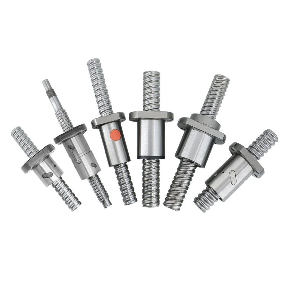
An undersized ball screw applies side torque to the guide even when you sized the guide correctly. The screw needs extra force to move the load, the carriage resists, and the difference resolves into side load on the rolling elements. Sizing the drive to the actual moving mass removes that contribution entirely.
A heavy machinery customer ran a 10 tonne worktable on an HGR guide driven by a screw that was too small for the mass. The mismatch produced about 20% additional side torque on the guide. Moving to an SFS ball screw removed the extra torque, cut the guide's side wear rate by 30%, and reduced energy consumption by 15% because the drive was no longer fighting the load.
Where loads are larger still, the SFE ball screw with a large lead and single nut is the better pairing. Its single-nut design removes one misalignment point, and the higher lead reduces the rotational force needed to move a heavy table. A wind turbine manufacturer building a blade assembly line paired SFE screws with HGR guides for the blade section tables, and the reduced torque let them specify a slightly smaller HGR size than the original plan without losing performance.
Lever 5: Sizing for Torque, Not Just Load
Guide sizing is regularly done on linear load alone, which under-specifies the carriage in any application where your centre of gravity is offset. Larger HGR sizes carry wider raceways and more rolling elements, so the same torque is distributed across a longer contact length.
| HGR size | Dynamic load capacity | Static torque capacity | Typical use |
|---|---|---|---|
| HGR15 | Low | Low | Light duty, high precision |
| HGR25 | Up to 18 kN | Around 1,200 N·m | General automation |
| HGR45 | Up to 50 kN | Over 4,000 N·m | Heavy machine tool, transfer lines |
| HGR65 | Highest in range | Highest in range | 10 tonne and above |
The practical consequence is simple to apply. An application carrying a 2,000 N·m torque load sits above the HGR25 figure, so moving to HGR45 is usually cheaper than rebuilding the drive train and mounting structure around a guide that is too small. Calculate both the linear load and the torque load before you select a size; using linear load alone is the single most common cause of under-specification.
Maintenance That Holds Torque Resistance
Lubrication is the cheapest of the six levers and the one most often skipped in a maintenance plan. HGR guides need lithium complex or synthetic grease, selected by operating temperature, applied every 3 to 6 months in industrial service or at the interval the manufacturer specifies. Without it, friction between rolling elements and raceways rises, wear becomes uneven, and torque resistance falls with it.
A packaging line that had no lubrication schedule lost about 40% of its torque resistance over two years. Re-lubrication restored most of the performance, and a centralized lubrication system removed the human variable so the interval held without supervision.
The Myth of Raw Torque Capacity
A higher torque rating does not by itself give you better behaviour. A system with generous capacity but uneven load distribution performs worse than a slightly smaller system that shares the load evenly across two rails and multiple carriages. Capacity sets the ceiling; configuration decides how much of that ceiling is actually available at the carriage.
Torque Checklist
- Two parallel rails with paired carriages on any axis with an offset load
- Parallelism verified by laser at about 0.05 mm per metre
- Intermediate support on rails longer than 2 m, and on HGR35 and above
- Drive screw sized to your moving mass, not to nominal thrust
- Guide size selected against the torque figure as well as the linear load
- Grease interval defined and either scheduled or automated
Frequently Asked Questions
Is one large rail as good as two smaller rails?
Rarely, when torque is present. A single rail concentrates every rotational force through one carriage, while two parallel rails split it across four contact points. In the stamping press case above, the change took service life from 12 months to 48 months without a larger guide.
How much rail deflection is acceptable?
On the 4 metre solar panel axis, 0.8 mm of deflection under 500 kg produced visible carriage tilt and measurable positioning error. Adding intermediate support brought it to 0.1 mm and removed 85% of the torque-related error. Treat sub-millimetre deflection on long spans as a torque problem rather than a stiffness problem.
Does a bigger ball screw always reduce side torque?
Only when the original screw was undersized. A screw matched to the moving mass removes the extra force the carriage has to resist. Where the mismatch was 20%, the change cut guide side wear by 30% and energy use by 15%; where the screw is already correct, a larger one adds inertia without benefit.
Talk to an Engineer
Need the torque load calculated for an offset centre of gravity?
Send us the moving mass, centre of gravity offset, stroke, speed and mounting arrangement. Our engineers return the HGR size, carriage configuration and drive recommendation, with a lead time, within one working day. Request a quote and technical review.
References
- Association for Manufacturing Technology. (2022). Linear Motion Systems: Load, Torque, and Alignment Best Practices.
- HLTNC. (2023). HGR Linear Guide Technical Specification and Application Guidelines.
- National Institute of Standards and Technology. (2021). Ball Screw Selection for High-Torque Linear Motion Applications.